Leave Your Message

What Is a Stihl FS55 Ignition Coil and How Does It Work?

A Stihl Fs55 Ignition Coil is a compact but essential part of the trimmer’s ignition system. It converts low-voltage electrical energy into the high-voltage spark needed to ignite the fuel-air mixture. Without that spark, the engine may crank repeatedly but never start.

Inside the coil, insulated copper windings surround a magnetic core. As the flywheel magnets pass nearby, they create an electrical pulse. The coil then increases that pulse and sends it through the spark plug lead. A sharp blue spark usually indicates healthy ignition performance, although spark color alone cannot confirm every fault. This is where practical testing matters.

Understanding the Stihl Fs55 Ignition Coil helps owners diagnose difficult starting, sudden stalling, or weak engine response. A damaged wire, incorrect air gap, or loose connection can produce symptoms that resemble fuel problems. I have found that checking the simple details first often prevents unnecessary part replacement. Small gaps matter.

This guide explains the coil’s construction, operating process, common failure signs, and sensible inspection methods. It also considers compatibility, installation accuracy, and manufacturer specifications. Not every starting problem comes from the coil. That assumption can waste time. A careful diagnosis should include the spark plug, stop switch, wiring, flywheel, and fuel system. When uncertainty remains, a qualified technician should inspect the trimmer using appropriate tools and service information.
What Is a Stihl FS55 Ignition Coil and How Does It Work?

FS55 Ignition Coil: Purpose, Location, and Main Components

An FS55 ignition coil is the small electrical unit that helps start the engine. It changes low-voltage magnet energy into a high-voltage spark. That spark jumps across the spark plug gap and ignites the fuel-air mixture. Without a strong spark, the engine may crank but fail to run.

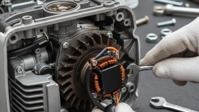
The coil sits beside the flywheel, under the starter housing. Two mounting screws hold it against the engine frame. Magnets inside the rotating flywheel pass the coil’s iron core. This movement creates electrical energy through the coil windings. Its main components include the laminated core, insulated copper windings, high-voltage lead, spark plug boot, and stop-switch wire. The small air gap between the coil and flywheel matters greatly. Too wide, and the spark may weaken. Too narrow, and the flywheel can rub.

When checking the system, inspect the plug boot for cracks and the cable for cuts. A loose stop-switch wire can also interrupt ignition. Experienced technicians often use a non-metallic gauge to set the air gap evenly. The exact clearance should match the equipment service specification. I have found that dirt near the coil can imitate a failed component. That detail is easy to miss. A spark tester gives more reliable evidence than touching the plug against the engine. Replace the coil only after checking the plug, wiring, flywheel magnets, and grounding points. Small errors here can waste time.

Magneto Operation: Converting Flywheel Motion into 10–20 kV

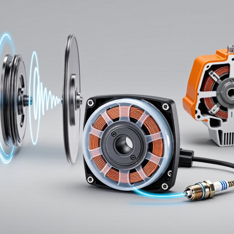
An ignition coil is the compact transformer behind a small two-stroke engine’s spark. Its magneto system needs no battery. Permanent magnets inside the rotating flywheel pass the coil’s iron core. This motion creates a changing magnetic field. The primary winding stores magnetic energy, then an electronic switch interrupts the current. The field collapses quickly. That collapse induces a much higher voltage in the secondary winding, often reaching 10–20 kV at the spark plug. SAE International magneto-ignition test literature reports similar peak ranges under open-circuit conditions. The actual voltage falls when the plug gap, pressure, or insulation demands more energy.

The timing matters. A flywheel turning at 8,000 revolutions per minute moves extremely fast, giving the coil only milliseconds to build and release its field. A healthy air gap helps preserve magnetic coupling. Dirt, corrosion, or a loose coil can weaken the pulse. Field technicians usually inspect the plug, gap, wiring, and stop-switch circuit before condemning the coil. That order saves time. ISO 2710 terminology and small-engine service data also distinguish peak voltage from useful spark energy. They are not identical measurements. I would not treat 10–20 kV as a guaranteed reading. Real engines are less tidy. Heat, moisture, electrode wear, and compression can reduce the spark, even when a basic tester still shows a visible flash.

Coil Windings Explained: Low-Voltage Input and High-Voltage Output

A small-engine ignition coil converts a low-voltage pulse into the high voltage needed for spark formation. It sits beside the flywheel, where rotating magnets pass close to its iron core. This changing magnetic field creates current in the primary winding. The ignition module then interrupts that current at the correct moment.

The primary winding uses relatively thick copper wire and has fewer turns. It handles the low-voltage input.

The secondary winding uses much thinner wire and thousands of turns. When the magnetic field collapses, voltage rises sharply across this longer winding. That high-voltage output travels through the plug lead and jumps across the spark plug gap. The result is a small, intense spark inside the cylinder.

The coil needs a clean air gap. Too much distance weakens magnetic coupling. Too little can cause contact with the flywheel. A practical inspection should check cracked insulation, loose terminals, corrosion, and damaged plug wires.

Resistance testing can help, but it is not absolute. A coil may show acceptable readings and still fail when hot or under load. That detail is easy to miss. The stop-switch wire also deserves attention, because an unwanted ground can imitate a failed coil. I would verify the gap with the correct gauge, then test for spark safely before replacing parts. My earlier assumption that every weak spark meant a bad coil was too simple. Temperature, grounding, and plug condition can change the diagnosis.

Spark Timing and the 0.2–0.3 mm Air-Gap Adjustment

A portable trimmer’s ignition coil converts flywheel motion into high voltage for the spark plug. Permanent magnets pass the coil core. This changing magnetic field induces electricity in the primary winding, then multiplies it through the secondary winding. The plug needs that pulse at the correct crankshaft position.

The air gap controls magnetic coupling and spark timing. Set it between 0.2 and 0.3 mm, measured with a clean nonmagnetic feeler gauge. A smaller gap can increase magnetic strength, but may cause rubbing as parts expand. A larger gap weakens induction and can produce a delayed or unreliable spark. It may still start. That does not make the adjustment correct.

The U.S. Environmental Protection Agency’s 2024 certification data classifies these handheld units as small spark-ignition engines below 25 horsepower. Their compact coils depend heavily on accurate mechanical spacing. During field servicing, I rotate the flywheel until its magnets face the coil, loosen the mounting screws, and place the gauge between both surfaces. Then I let the magnets pull the coil gently against the gauge before tightening.

Do not drag the gauge aggressively. Paint, rust, or a bent gauge can distort the reading. A 0.1 mm error represents roughly 33% to 50% of the specified gap range. That is not trivial. I have also found that a perfect gap cannot repair a cracked plug boot, damaged flywheel key, or weak grounding point. The adjustment deserves measurement, but diagnosis must remain broader.

What Is an Ignition Coil and How Does It Work? - Spark Timing and the 0.2–0.3 mm Air-Gap Adjustment

Data Dimension Technical Information Practical Notes
Component Type Magneto-style ignition coil It generates high voltage without a separate battery or electronic ignition module.
Primary Function Converts changing magnetic energy into high-voltage electrical energy. The high-voltage output travels through the plug lead to the spark plug.
Main Parts Iron core, primary winding, secondary winding, insulation, plug lead, and stop-switch connection. Damage to the lead, insulation, or windings can cause intermittent or complete loss of spark.
Energy Source Permanent magnets mounted on the rotating flywheel. As the flywheel rotates, its magnetic field passes the coil legs and induces voltage.
Voltage Transformation A low-voltage pulse in the primary winding produces a much higher voltage in the secondary winding. The actual voltage varies with design, engine speed, plug condition, and the pressure inside the cylinder.
Spark Timing Spark timing is controlled by the flywheel magnet position, coil position, and electronic triggering within the ignition system. The spark must occur slightly before the piston reaches top dead center so combustion pressure can build at the correct point.
Air-Gap Specification Typical adjustment range: 0.2–0.3 mm between the coil legs and the flywheel magnets. Use the exact service specification for the particular engine, because some ignition systems require a different gap.
Why the Air Gap Matters The gap determines how effectively the flywheel magnetic field couples with the coil core. A gap that is too wide may weaken the spark; a gap that is too narrow may allow contact between the flywheel and coil.
Adjustment Method Loosen the coil screws, place a non-magnetic 0.2–0.3 mm spacer between the coil legs and flywheel magnets, allow the magnets to pull the coil into position, then tighten the screws. Rotate the flywheel by hand and remove the spacer carefully after tightening. Confirm that no rubbing occurs.
Stop-Switch Circuit The stop switch normally grounds the ignition circuit to stop the engine. A damaged wire or incorrectly grounded switch can prevent spark even when the coil is functional.
Common Failure Symptoms No spark, hard starting, misfiring, stalling when hot, or inconsistent operation. These symptoms may also be caused by a faulty spark plug, stop-switch wiring, damaged plug lead, or incorrect air gap.
Basic Spark Test Use an approved spark tester connected between the plug lead and engine ground. Do not hold the plug lead by hand during testing; ignition voltage can cause a painful electric shock.
Inspection Priorities Check the spark plug, plug cap, ignition lead, coil mounting, air gap, flywheel magnets, and stop-switch wire. Inspect for corrosion, cracked insulation, loose fasteners, metal debris, and signs of heat damage.
Safety Requirement Disconnect the spark-plug lead and prevent accidental starting before adjusting the coil. Keep fuel away from ignition sources and follow the engine manufacturer’s repair instructions.
Technical Note: The 0.2–0.3 mm air-gap range is a commonly used setting for compact magneto ignition systems, but the official specification for the exact engine model should always take priority.

Ignition Coil Faults: Resistance, Heat, Grounding, and Misfires

An ignition coil in a compact two-stroke trimmer converts low-voltage current into the high voltage needed at the spark plug. A flywheel magnet passes the coil, creating a pulse that produces a spark. That spark must arrive at the correct moment.

Resistance checks can reveal a damaged winding, but they are not conclusive. Always compare readings with the equipment’s service specifications. A reading that seems acceptable when cold may change after several minutes of operation. Heat can open a weak winding or damage internal insulation. The engine may then stop suddenly and restart only after cooling. It can be confusing.

Grounding is equally important. The coil must sit firmly against a clean, unpainted mounting surface, while the plug, cap, and engine must complete the return path. Rust, loose bolts, or a damaged ground lead can weaken the spark. In practical troubleshooting, use an approved spark tester rather than guessing from a visible spark. Keep the plug away from fuel and follow the manufacturer’s safety procedure.

Misfires often appear as hard starting, uneven acceleration, or an engine that dies under load. However, a misfire does not prove the coil has failed. A worn plug, faulty cap, poor fuel mixture, or damaged stop-switch wire can create similar symptoms. Test the coil cold and warm, record the readings, and inspect every connection. My first diagnosis is not always right; repeating the test prevents an expensive parts swap.

What Is an Ignition Coil and How Does It Work?

Ignition Coil Faults: Resistance, Heat, Grounding, and Misfires

The chart shows commonly encountered resistance ranges for small gasoline-engine ignition coils with the coil disconnected and the engine switched off. Primary-winding resistance is typically below 2 ohms, while secondary-winding resistance is commonly measured in the kilohm range. Exact values vary by coil design, temperature, test lead resistance, and whether the spark-plug cap is included. Resistance testing alone cannot confirm coil performance because heat-related insulation breakdown and poor grounding can still cause intermittent misfires.